Friday, October 2, 2020

Back EMF in DC Motor


Back EMF in DC Motor


When the current-carrying conductor placed in a magnetic field, the torque induces on the conductor, the torque rotates the conductor which cuts the flux of the magnetic field. According to the Electromagnetic Induction Phenomenon “when the conductor cuts the magnetic field, EMF induces in the conductor”.

The Fleming right-hand rule determines the direction of the induced EMF.

According to Fleming Right Hand Rule, if we hold our thumb, middle finger and index finger of the right hand by an angle of 90°, then the index finger represents the direction of the magnetic field. The thumb shows the direction of motion of the conductor and the middle finger represents the emf induces on the conductor.

On applying the right-hand rule in the figure shown below, it is seen that the direction of the induced emf is opposite to the applied voltage. Thereby the emf is known as the counter emf or back emf.

The back emf is developed in series with the applied voltage, but opposite in direction, i.e., the back emf opposes the current which causes it.

The magnitude of the back emf is given by the same expression shown below:

back-emf-in-dc-motor-eq

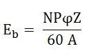
Where Eb is the induced emf of the motor known as Back EMF, A is the number of parallel paths through the armature between the brushes of opposite polarity. P is the number of poles, N is the speed, Z is the total number of conductors in the armature and ϕ is the useful flux per pole.

A simple conventional circuit diagram of the machine working as a motor is shown in the diagram below:


In this case, the magnitude of the back emf is always less than the applied voltage. The difference between the two is nearly equal when the motor runs under normal conditions.

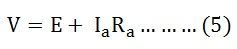
The current induces on the motor because of the main supply. The relation between the main supply, back emf and armature current is given as E= V – IaRa.

Advantages of Back Emf in DC Motor

1. The back emf opposes the supply voltage. The supply voltage induces the current in the coil which rotates the armature. The electrical work required by the motor for causing the current against the back emf is converted into mechanical energy. And that energy is induced in the armature of the motor. Thus, we can say that energy conversion in the DC motor is possible only because of the back emf.

The mechanical energy induced in the motor is the product of the back emf and the armature current, i.e., EbIa.

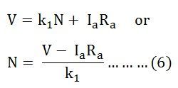
2. The back emf makes the DC motor self-regulating machine, i.e., the back emf develops the armature current according to the need of the motor. The armature current of the motor is calculated as:armature-current

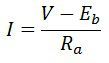
Let’s understand how the back emf makes motor self-regulating.

  • Consider the motor is running at no-load condition. At no load, the DC motor requires small torque for controlling the friction and windage loss. The motor withdraws less current. As the back emf depends on the current their value also decreases. The magnitude of the back EMF is nearly equal to the supply voltage.
  • If the sudden load is applied to the motor, the motor becomes slow down. As the speed of the motor decreases, the magnitude of their back emf also falls down. The small back emf withdraw heavy current from the supply. The large armature current induces the large torque in the armature, which is the need of the motor. Thus, the motor moves continuously at a new speed.
  • If the load on the motor is suddenly reduced, the driving torque on the motor is more than the load torque. The driving torque increases the speed of the motor which also increases their back emf.  The high value of back emf decreases the armature current. The small magnitude of armature current develops less driving torque, which is equal to the load torque. And the motor will rotate uniformly at the new speed.

relation between Mechanical power (Pm), supply voltage (Vt) and Back EMF (Eb)

The back emf in the dc motor is expressed as:

back-emf-equation-1

Where Eb – Back Emf
Ia – Armature Current
Vt – Terminal Voltage
Ra – Resistance of Armature

The maximum power developed on the motor is expressed by

back-emf-equation-2

On differentiating the above equation we getback-emf-equation-3

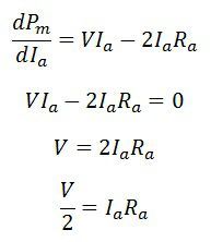
From the back emf equation, we get

back-emf-equation-4

On substituting the IaRa in the above equation, we get

back-emf-equation-5
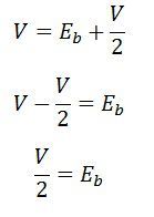
The above equation shows that the maximum power is developed in the motor when the back emf is equal to half of the supply voltage.


Types of DC Motor

Classification Of DC Motor:-


Separately Excited DC Motor


A separately excited DC motor the supply is given separately to the field and armature windings. The main distinguishing fact in these types of DC motor is that, the armature current does not flow through the field windings, as the field winding is energized from a separate external source of DC current as shown in the figure beside.

From the torque equation of DC motor we know Tg = Ka φ Ia So the torque in this case can be varied by varying field flux φ, independent of the armature current Ia.

Self Excited DC Motor


As the name implies self-excited, hence, in this type of motor, the current in the windings is supplied by the machine or motor itself. Self-excited DC Motor is further divided into shunt wound, and series wound motor. They are explained below in detail.

Shunt Wound Motor

This is the most common types of DC Motor. Here the field winding is connected in parallel with the armature as shown in the figure below:


In case of a shunt wound DC motor or more specifically shunt wound self excited DC motor, the field windings are exposed to the entire terminal voltage as they are connected in parallel to the armature winding as shown in the figure below.

To understand the characteristic of these types of DC motor, lets consider the basic voltage equation given by,

[Where, E, Eb, Ia, Ra are the supply voltage, back emf, armature current and armature resistance respectively]


Now substituting Eb from equation (2) to equation (1) we get,

In a series wound DC motor, the speed varies with load. And operation wise this is its main difference from a shunt wound DC motor.

The torque equation of a DC motor resembles,

This is similar to the equation of a straight line, and we can graphically representing the torque speed characteristic of a shunt wound self excited DC motor as

The shunt wound DC motor is a constant speed motor, as the speed does not vary here with the variation of mechanical load on the output.


Series Wound Motor

In the series motor, the field winding is connected in series with the armature winding. The connection diagram is shown below:


In case of a series wound self excited DC motor or simply series wound DC motor, the entire armature current flows through the field winding as its connected in series to the armature winding. 

Now to determine the torque speed characteristic of these types of DC motor, lets get to the torque speed equation.

From the circuit diagram we can see that the voltage equation gets modified to

Where as back emf remains Eb = kaφω

Neglecting saturation we get,

[since field current = armature current]

From equation (5) and (6)

From this equation we obtain the torque speed characteristic as

In a series wound DC motor, the speed varies with load. And operation wise this is its main difference from a shunt wound DC motor.

Compound Wound Motor

The compound excitation characteristic in a DC motor can be obtained by combining the operational characteristic of both the shunt and series excited DC motor. The compound wound self excited DC motor or simply compound wound DC motor essentially contains the field winding connected both in series and in parallel to the armature winding as shown in the figure below:

The compound motor is further subdivided as Cumulative Compound Motor and Differential Compound Motor. In a cumulative compound motor the flux produced by both the windings is in the same direction, i.e.

types-of-motor-eq11

In differential compound motor, the flux produced by the series field windings is opposite to the flux produced by the shunt field winding, i.e.

types-of-motor-eq12

The positive and negative sign indicates that the direction of the flux produced in the field windings.


Both the cumulative compound and differential compound DC motor can either be of short shunt or long shunt type depending on the nature of arrangement.

Short Shunt DC Motor

If the shunt field winding is only parallel to the armature winding and not the series field winding then its known as short shunt DC motor or more specifically short shunt type compound wound DC motor.

The circuit diagram of a short shunt DC motor is shown in the diagram below.


Long Shunt DC Motor

If the shunt field winding is parallel to both the armature winding and the series field winding then it’s known as long shunt type compounded wound DC motor or simply long shunt DC motor.

The circuit diagram of a long shunt DC motor is shown in the diagram below.


Permanent Magnet DC Motor

A DC Motor whose poles are made of Permanent Magnets is known as Permanent Magnet DC (PMDC) Motor. The magnets are radially magnetized and are mounted on the inner periphery of the cylindrical steel stator. The stator of the motor serves as  a return path for the magnetic flux. The rotor has a DC armature, with commutator segments and brushes.

The cross-sectional view of the 2 pole PMDC motor is  shown in the figure below.


The Permanent Magnet DC motor generally operates on 6 V, 12 V or 24 Volts DC supply obtained from the batteries or rectifiers. The interaction between the axial current carrying rotor conductors and the magnetic flux produced by the permanent magnet results in the generation of the torque.

The circuit diagram of the PMDC is shown below.


In conventional DC motor, the generated or back EMF is given by the equation shown below.

PMDC-MOTOR-EQ-1

The electromagnetic torque is given as

PMDC-MOTOR-EQ-2

In Permanent Magnet DC motor, the value of flux ϕ is constant. Therefore, the above equation (1) and (2) becomes

PMDC-MOTOR-EQ-3

Considering the above circuit diagram the following equations are expressed.

PMDC-MOTOR-EQ-4

Putting the value of E from the equation (3) in equation (5) we get

PMDC-MOTOR-EQ-5

Where k1 = k ϕ and is known as speed-voltage constant or torque constant. Its value depends upon the number of field poles and armature conductors.

The speed control of the PMDC motor cannot be controlled by using flux control method as the flux remains constant in this type of motor. Both speed and torque can be controlled by armature voltage control, armature rheostat control, and chopper control methods. These motors are used where the motor speed below the base speed is required as they cannot be operated above the base speed.

Types of Permanent Magnet Materials

There are three types of Permanent Magnet Materials used in PMDC Motor. The detailed information is given below.

Alnicos

Alnicos has a low coercive magnetizing intensity and high residual flux density. Hence, it is used where low current and high voltage is required.

Ferrites

They are used in cost sensitive applications such as Air conditioners, compressors, and refrigerators.

Rare earths

Rare earth magnets are made of Samarium cobalt, neodymium-iron-boron. They have a high residual flux and high coercive magnetizing intensity. The rare earth magnets are exempted from demagnetizing problems due to armature reaction. It is an expensive material.

The Neodymium iron boron is cheaper as compared to Samarium cobalt. But it can withstand higher temperature. Rare earth magnets are used for size-sensitive applications. They are used in automobiles, servo industrial drives and in large industrial motors.

Applications of the Permanent Magnet DC Motor

The PMDC motors are used in various applications ranging from fractions to several horsepower.  They are developed up to about 200 kW for use in various industries. The following applications are given below.

  • PMDC motors are mainly used in automobiles to operate windshield wipers and washers, to raise the lower windows, to drive blowers for heaters and air conditioners etc.
  • They are also used in computer drives.
  • These types of motors are also used in toy industries.
  • PMDC motors are used in electric toothbrushes, portable vacuum cleaners, food mixers.
  • Used in a portable electric tool such as drilling machines, hedge trimmers etc.


EMF Equation of DC Machine


EMF Equation of DC Machine

The DC machine e.m.f can be defined as when the armature in the dc machine rotates, the voltage can be generated within the coils. In a generator, the e.m.f of rotation can be called the generated emf, and Er=Eg. In the motor, the emf of rotation can be called as counter or back emf, and Er=Eb.

Let Φ is the useful flux for every pole within webers
P is the total number of poles
z is the total number of conductors within the armature
n is the rotation speed for an armature in the revolution for each second
A is the no. of parallel lane throughout the armature among the opposite polarity brushes.
Z/A is the no. of armature conductor within series for each parallel lane
As the flux for each pole is ‘Φ’, every conductor slashes a flux ‘PΦ’ within a single revolution.

The voltage produced for each conductor = flux slash for each revolution in WB / Time taken for a single revolution within seconds

As ‘n’ revolutions are completed within a single second and 1 revolution will be completed within a 1/n second. Thus the time for a single armature revolution is a 1/n sec.

The standard value of produced voltage for each conductor

p Φ/1/n = np Φ volts

The voltage produced (E) can be decided with the no.of armature conductors within series I any single lane among the brushes thus, the whole voltage produced

E = standard voltage for each conductor x no. of conductors within series for each lane

E = n.P.Φ x Z/A

The above equation is the e.m.f. the equation of the DC machine.

Thursday, October 1, 2020

Operating Principle and Construction of DC Machine

Operating Principle of DC Machine:-

DC Machine is an electro-mechanical energy conversion device. There are two types of DC machines; one is the DC generator, and another one is known as DC motor.

The basic working principle of a DC motor is: "whenever a current carrying conductor is placed in a magnetic field, it experiences a mechanical force". The direction of this force is given by Fleming's left-hand rule and its magnitude is given by F = BIL. Where, B = magnetic flux density, I = current and L = length of the conductor within the magnetic field.

Fleming's left hand rule: If we stretch the first finger, second finger and thumb of our left hand to be perpendicular to each other, and the direction of magnetic field is represented by the first finger, direction of the current is represented by the second finger, then the thumb represents direction of the force experienced by the current carrying conductor.


Construction of DC Machine:-


DC Generator is an electrical device which converts mechanical energy into electrical energy. It mainly consists of three main parts, i.e. magnetic field system, armature and commutator and brush gear. The other parts of a DC Generator are magnetic frame and yoke, pole core and pole shoes, field or exciting coils, armature core and windings, brushes, end housings, bearings and shafts. 

The rotating electrical or DC machine has mainly two parts; one is Stator, and another one is Rotar. The stator and rotor are separated from each other by an air gap. The stator is the outer frame of the machine and is immovable. The rotor is free to move and is the inner part of the machine.

Both the stator and the rotor are made of ferromagnetic materials. Slots are cut on the inner periphery of the stator and the outer periphery of the rotor. Conductors are placed in the slots of the stator or rotor. They are interconnected to form windings.

The windings in which voltage is induced is called the Armature windings. The winding through which a current is passed to produce the main flux is called the Field windings. To provide main flux in some of the machine permanent magnets is also used.


A DC Motor is Constructed with :-
  • Magnetic Field System of DC Generator
  • Magnetic Frame or Yoke
  • Pole core and pole shoes
  • Field or exciting coils
  • Armature of DC Generator
  • Armature cores
  • Armature winding
  • Commutator
  • Brushes
  • End housing
  • Bearing
  • Shaft

Magnetic Field System of DC Generator


The Magnetic Field System is the stationary or fixed part of the machine. It produces the main magnetic flux. The magnetic field system consists of Mainframe or Yoke, Pole core and Pole shoes and Field or Exciting coils. These various parts of DC Generator are described below in detail.

Magnetic Frame and Yoke

The outer hollow cylindrical frame to which main poles and inter-poles are fixed and by means of which the machine is fixed to the foundation is known as Yoke. It is made of cast steel or rolled steel for the large machines and for the smaller size machine the yoke is generally made of cast iron.

The two main purposes of the yoke are as follows:-

  • It supports the pole cores and provides mechanical protection to the inner parts of the machines.
  • It provides a low reluctance path for the magnetic flux.

Pole Core and Pole Shoes

The Pole Core and Pole Shoes are fixed to the magnetic frame or yoke by bolts. Since the poles, project inwards they are called salient poles. Each pole core has a curved surface. Usually, the pole core and shoes are made of thin cast steel or wrought iron laminations which are riveted together under hydraulic pressure. The poles are laminated to reduce the Eddy Current loss.


Field or Exciting Coils

Each pole core has one or more field coils (windings) placed over it to produce a magnetic field. The enamelled copper wire is used for the construction of field or exciting coils. The coils are wound on the former and then placed around the pole core.

Armature of DC Generator

The rotating part of the DC machine or a DC Generator is called the Armature. The armature consists of a shaft upon which a laminated cylinder, called Amature Core is placed.

Armature Core


The armature core of DC Generator is cylindrical in shape and keyed to the rotating shaft. At the outer periphery of the armature has grooves or slots which accommodate the armature winding as shown in the figure below.

The armature core of a DC generator or machine serves the following purposes.

  • It houses the conductors in the slots.
  • It provides an easy path for the magnetic flux.

Armature Winding

The insulated conductors are placed in the slots of the armature core. The conductors are wedged, and bands of steel wire wound around the core and are suitably connected. This arrangement of conductors is called Armature Winding. The armature winding is the heart of the DC Machine.

Armature winding is a place where the conversion of power takes place. In the case of a DC Generator here, mechanical power is converted into electrical power. On the basis of connections, the windings are classified into two types named as Lap Winding and Wave Winding.

  • Lap Winding

In lap winding, the conductors are connected in such a way that the number of parallel paths is equal to the number of poles. Thus, if a machine has P poles and Z armature conductors, then there will be P parallel paths, each path will have Z/P conductors connected in series.

In lap winding, the number of brushes is equal to the number of parallel paths. Out of which half the brushes are positive and the remaining half are negative.

  • Wave Winding

In wave winding, the conductors are so connected that they are divided into two parallel paths irrespective of the number of poles of the machine. Thus, if the machine has Z armature conductors, there will be only two parallel paths each having Z/2 conductors in series. In this case number of brushes is equal to two, i.e. number of parallel paths.

Commutator in DC Generator


The commutator, which rotates with the armature, is cylindrical in shape and is made from a number of wedge-shaped hard drawn copper bars or segments insulated from each other and from the shaft. The segments form a ring around the shaft of the armature. Each commutator segment is connected to the ends of the armature coils.

It is the most important part of a DC machine and serves the following purposes.

  • It connects the rotating armature conductors to the stationary external circuit through brushes.
  • It converts the induced alternating current in the armature conductor into the unidirectional current in the external load circuit in DC Generator action, whereas it converts the alternating torque into unidirectional (continuous) torque produced in the armature in motor action.

Brushes

Carbon brushes are placed or mounted on the commutator and with the help of two or more carbon brushes current is collected from the armature winding. Each brush is supported in a metal box called a brush box or brush holder. The brushes are pressed upon the commutator and form the connecting link between the armature winding and the external circuit.

The pressure exerted by the brushes on the commutator can be adjusted and is maintained at a constant value by means of springs. With the help of the brushes, the current which is produced on the windings is passed on to the commutator and then to the external circuit.

They are usually made of high-grade carbon because carbon is conducting material and at the same time in powdered form provides a lubricating effect on the commutator surface.


End Housings

End housings are attached to the ends of the Mainframe and provide support to the bearings. The front housings support the bearing and the brush assemblies whereas the rear housings usually support the bearings only.

Bearings

The ball or roller bearings are fitted in the end housings. The function of the bearings is to reduce friction between the rotating and stationary parts of the machine. Mostly high carbon steel is used for the construction of bearings as it is a very hard material.

Shaft

The shaft is made of mild steel with a maximum breaking strength. The shaft is used to transfer mechanical power from or to the machine. The rotating parts like armature core, commutator, cooling fans, etc. are keyed to the shaft.