A separately excited DC motor the supply is given separately to the field and armature windings. The main distinguishing fact in these types of DC motor is that, the armature current does not flow through the field windings, as the field winding is energized from a separate external source of DC current as shown in the figure beside.
From the torque equation of DC motor we know Tg = Ka φ Ia So the torque in this case can be varied by varying field flux φ, independent of the armature current Ia.
Self Excited DC Motor
As the name implies self-excited, hence, in this type of motor, the current in the windings is supplied by the machine or motor itself. Self-excited DC Motor is further divided into shunt wound, and series wound motor. They are explained below in detail.
Shunt Wound Motor
This is the most common types of DC Motor. Here the field winding is connected in parallel with the armature as shown in the figure below:
In case of a shunt wound DC motor or more specifically shunt wound self excited DC motor, the field windings are exposed to the entire terminal voltage as they are connected in parallel to the armature winding as shown in the figure below.
To understand the characteristic of these types of DC motor, lets consider the basic voltage equation given by,
[Where, E, Eb, Ia, Ra are the supply voltage, back emf, armature current and armature resistance respectively]
Now substituting Eb from equation (2) to equation (1) we get,
In a series wound DC motor, the speed varies with load. And operation wise this is its main difference from a shunt wound DC motor.
The torque equation of a DC motor resembles,
This is similar to the equation of a straight line, and we can graphically representing the torque speed characteristic of a shunt wound self excited DC motor as
The shunt wound DC motor is a constant speed motor, as the speed does not vary here with the variation of mechanical load on the output.
Series Wound Motor
In the series motor, the field winding is connected in series with the armature winding. The connection diagram is shown below:
In case of a series wound self excited DC motor or simply series wound DC motor, the entire armature current flows through the field winding as its connected in series to the armature winding.
Now to determine the torque speed characteristic of these types of DC motor, lets get to the torque speed equation.
From the circuit diagram we can see that the voltage equation gets modified to
Where as back emf remains Eb = kaφω
Neglecting saturation we get,
[since field current = armature current]
From equation (5) and (6)
From this equation we obtain the torque speed characteristic as
In a series wound DC motor, the speed varies with load. And operation wise this is its main difference from a shunt wound DC motor.
Compound Wound Motor
The compound excitation characteristic in a DC motor can be obtained by combining the operational characteristic of both the shunt and series excited DC motor. The compound wound self excited DC motor or simply compound wound DC motor essentially contains the field winding connected both in series and in parallel to the armature winding as shown in the figure below:
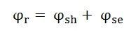
The compound motor is further subdivided as Cumulative Compound Motor and Differential Compound Motor. In a cumulative compound motor the flux produced by both the windings is in the same direction, i.e.
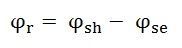
In differential compound motor, the flux produced by the series field windings is opposite to the flux produced by the shunt field winding, i.e.
The positive and negative sign indicates that the direction of the flux produced in the field windings.
Both the cumulative compound and differential compound DC motor can either be of short shunt or long shunt type depending on the nature of arrangement.
Short Shunt DC Motor
If the shunt field winding is only parallel to the armature winding and not the series field winding then its known as short shunt DC motor or more specifically short shunt type compound wound DC motor.
The circuit diagram of a short shunt DC motor is shown in the diagram below.
Long Shunt DC Motor
If the shunt field winding is parallel to both the armature winding and the series field winding then it’s known as long shunt type compounded wound DC motor or simply long shunt DC motor.
The circuit diagram of a long shunt DC motor is shown in the diagram below.
Permanent Magnet DC Motor
A DC Motor whose poles are made of Permanent Magnets is known as Permanent Magnet DC(PMDC) Motor. The magnets are radially magnetized and are mounted on the inner periphery of the cylindrical steel stator. The stator of the motor serves as a return path for the magnetic flux. The rotor has a DC armature, with commutator segments and brushes.
The cross-sectional view of the 2 pole PMDC motor is shown in the figure below.
The Permanent Magnet DC motor generally operates on 6 V, 12 V or 24 Volts DC supply obtained from the batteries or rectifiers. The interaction between the axial current carrying rotor conductors and the magnetic flux produced by the permanent magnet results in the generation of the torque.
The circuit diagram of the PMDC is shown below.
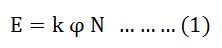
In conventional DC motor, the generated or back EMF is given by the equation shown below.
The electromagnetic torque is given as
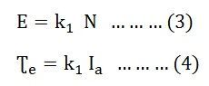
In Permanent Magnet DC motor, the value of flux ϕ is constant. Therefore, the above equation (1) and (2) becomes
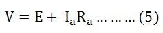
Considering the above circuit diagram the following equations are expressed.
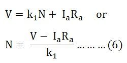
Putting the value of E from the equation (3) in equation (5) we get
Where k1 = k ϕ and is known as speed-voltage constant or torque constant. Its value depends upon the number of field poles and armature conductors.
The speed control of the PMDC motor cannot be controlled by using flux control method as the flux remains constant in this type of motor. Both speed and torque can be controlled by armature voltage control, armature rheostat control, and chopper control methods. These motors are used where the motor speed below the base speed is required as they cannot be operated above the base speed.
Types of Permanent Magnet Materials
There are three types of Permanent Magnet Materials used in PMDC Motor. The detailed information is given below.
Alnicos
Alnicos has a low coercive magnetizing intensity and high residual flux density. Hence, it is used where low current and high voltage is required.
Ferrites
They are used in cost sensitive applications such as Air conditioners, compressors, and refrigerators.
Rare earths
Rare earth magnets are made of Samarium cobalt, neodymium-iron-boron. They have a high residual flux and high coercive magnetizing intensity. The rare earth magnets are exempted from demagnetizing problems due to armature reaction. It is an expensive material.
The Neodymium iron boron is cheaper as compared to Samarium cobalt. But it can withstand higher temperature. Rare earth magnets are used for size-sensitive applications. They are used in automobiles, servo industrial drives and in large industrial motors.
Applications of the Permanent Magnet DC Motor
The PMDC motors are used in various applications ranging from fractions to several horsepower. They are developed up to about 200 kW for use in various industries. The following applications are given below.
PMDC motors are mainly used in automobiles to operate windshield wipers and washers, to raise the lower windows, to drive blowers for heaters and air conditioners etc.
They are also used in computer drives.
These types of motors are also used in toy industries.
PMDC motors are used in electric toothbrushes, portable vacuum cleaners, food mixers.
Used in a portable electric tool such as drilling machines, hedge trimmers etc.


very nice article
ReplyDelete