The basic working principle of a DC motor is: "whenever a current carrying conductor is placed in a magnetic field, it experiences a mechanical force". The direction of this force is given by Fleming's left-hand rule and its magnitude is given by F = BIL. Where, B = magnetic flux density, I = current and L = length of the conductor within the magnetic field.
Fleming's left hand rule: If we stretch the first finger, second finger and thumb of our left hand to be perpendicular to each other, and the direction of magnetic field is represented by the first finger, direction of the current is represented by the second finger, then the thumb represents direction of the force experienced by the current carrying conductor.

Construction of DC Machine:-
The rotating electrical or DC machine has mainly two parts; one is Stator, and another one is Rotar. The stator and rotor are separated from each other by an air gap. The stator is the outer frame of the machine and is immovable. The rotor is free to move and is the inner part of the machine.
Both the stator and the rotor are made of ferromagnetic materials. Slots are cut on the inner periphery of the stator and the outer periphery of the rotor. Conductors are placed in the slots of the stator or rotor. They are interconnected to form windings.
The windings in which voltage is induced is called the Armature windings. The winding through which a current is passed to produce the main flux is called the Field windings. To provide main flux in some of the machine permanent magnets is also used.

- Magnetic Field System of DC Generator
- Magnetic Frame or Yoke
- Pole core and pole shoes
- Field or exciting coils
- Armature of DC Generator
- Armature cores
- Armature winding
- Commutator
- Brushes
- End housing
- Bearing
- Shaft
Magnetic Field System of DC Generator
The Magnetic Field System is the stationary or fixed part of the machine. It produces the main magnetic flux. The magnetic field system consists of Mainframe or Yoke, Pole core and Pole shoes and Field or Exciting coils. These various parts of DC Generator are described below in detail.
Magnetic Frame and Yoke
The outer hollow cylindrical frame to which main poles and inter-poles are fixed and by means of which the machine is fixed to the foundation is known as Yoke. It is made of cast steel or rolled steel for the large machines and for the smaller size machine the yoke is generally made of cast iron.
The two main purposes of the yoke are as follows:-
- It supports the pole cores and provides mechanical protection to the inner parts of the machines.
- It provides a low reluctance path for the magnetic flux.
Pole Core and Pole Shoes
The Pole Core and Pole Shoes are fixed to the magnetic frame or yoke by bolts. Since the poles, project inwards they are called salient poles. Each pole core has a curved surface. Usually, the pole core and shoes are made of thin cast steel or wrought iron laminations which are riveted together under hydraulic pressure. The poles are laminated to reduce the Eddy Current loss.

Field or Exciting Coils
Each pole core has one or more field coils (windings) placed over it to produce a magnetic field. The enamelled copper wire is used for the construction of field or exciting coils. The coils are wound on the former and then placed around the pole core.
Armature of DC Generator
The rotating part of the DC machine or a DC Generator is called the Armature. The armature consists of a shaft upon which a laminated cylinder, called Amature Core is placed.
Armature Core

The armature core of DC Generator is cylindrical in shape and keyed to the rotating shaft. At the outer periphery of the armature has grooves or slots which accommodate the armature winding as shown in the figure below.
The armature core of a DC generator or machine serves the following purposes.
- It houses the conductors in the slots.
- It provides an easy path for the magnetic flux.
Armature Winding
The insulated conductors are placed in the slots of the armature core. The conductors are wedged, and bands of steel wire wound around the core and are suitably connected. This arrangement of conductors is called Armature Winding. The armature winding is the heart of the DC Machine.
Armature winding is a place where the conversion of power takes place. In the case of a DC Generator here, mechanical power is converted into electrical power. On the basis of connections, the windings are classified into two types named as Lap Winding and Wave Winding.
- Lap Winding
In lap winding, the conductors are connected in such a way that the number of parallel paths is equal to the number of poles. Thus, if a machine has P poles and Z armature conductors, then there will be P parallel paths, each path will have Z/P conductors connected in series.
In lap winding, the number of brushes is equal to the number of parallel paths. Out of which half the brushes are positive and the remaining half are negative.
- Wave Winding
In wave winding, the conductors are so connected that they are divided into two parallel paths irrespective of the number of poles of the machine. Thus, if the machine has Z armature conductors, there will be only two parallel paths each having Z/2 conductors in series. In this case number of brushes is equal to two, i.e. number of parallel paths.
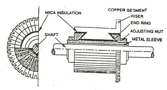
Commutator in DC Generator

The commutator, which rotates with the armature, is cylindrical in shape and is made from a number of wedge-shaped hard drawn copper bars or segments insulated from each other and from the shaft. The segments form a ring around the shaft of the armature. Each commutator segment is connected to the ends of the armature coils.
It is the most important part of a DC machine and serves the following purposes.
- It connects the rotating armature conductors to the stationary external circuit through brushes.
- It converts the induced alternating current in the armature conductor into the unidirectional current in the external load circuit in DC Generator action, whereas it converts the alternating torque into unidirectional (continuous) torque produced in the armature in motor action.
Brushes
Carbon brushes are placed or mounted on the commutator and with the help of two or more carbon brushes current is collected from the armature winding. Each brush is supported in a metal box called a brush box or brush holder. The brushes are pressed upon the commutator and form the connecting link between the armature winding and the external circuit.
The pressure exerted by the brushes on the commutator can be adjusted and is maintained at a constant value by means of springs. With the help of the brushes, the current which is produced on the windings is passed on to the commutator and then to the external circuit.
They are usually made of high-grade carbon because carbon is conducting material and at the same time in powdered form provides a lubricating effect on the commutator surface.
End Housings
End housings are attached to the ends of the Mainframe and provide support to the bearings. The front housings support the bearing and the brush assemblies whereas the rear housings usually support the bearings only.
Bearings
The ball or roller bearings are fitted in the end housings. The function of the bearings is to reduce friction between the rotating and stationary parts of the machine. Mostly high carbon steel is used for the construction of bearings as it is a very hard material.
Shaft
The shaft is made of mild steel with a maximum breaking strength. The shaft is used to transfer mechanical power from or to the machine. The rotating parts like armature core, commutator, cooling fans, etc. are keyed to the shaft.
very useful article
ReplyDelete